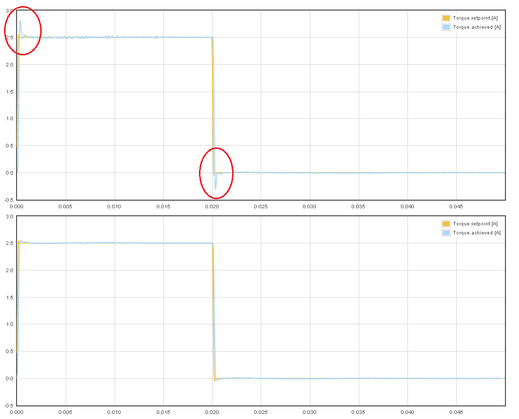
Latest innovation made to IONI firmware allows generating 15% higher output voltage for 3 phase AC motors which in practice means 15% greater maximum possible speed of motor. This is achieved by by altering the duty cycle generation of power stage so that it’s being utilized better for this kind of waveforms.
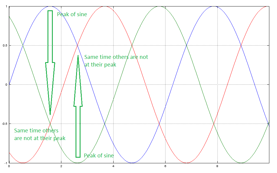
By looking the typical 3-phase motor voltage waveforms below, one can notice the peaks of sine waves occur one-at-a-time which means there is some headroom in the opposing polarity waves.
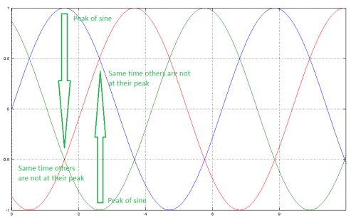
Standard 3 phase sinusoidal waveforms. Range from 1 to -1 means it uses full output voltage span available in drive (i.e. 0V to 55V)
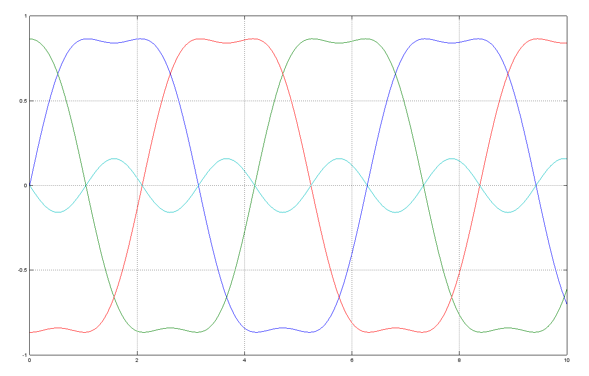
We can utilize these empty gaps by shifting all three waves up and down so that empty gaps become filled.
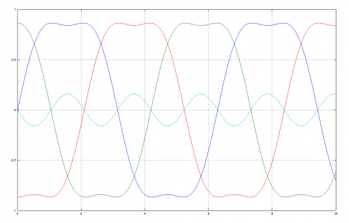
Same signals with summed third harmonic (cyan) to all phase values. This reduces peak amplitude of all signals by 15% without affecting to any phase-to-phase waveform shape or amplitude. In other words, motor sees no difference between this and the original.
After this step, we can multiply them by 1.15 without exceeding the maximum range of +/-1. This method has been tested and it works flawlessly. Same smoothness but just a bit higher speed range is available from the drive. The trick effectively does same as increasing drive supply voltage from 55 V to 64 V without actually increasing it.
This, and as many as possible, new features of IONI will be ported back to ARGON as soon as the IONI is out.