Final servo drive enclosures

After a long wait, the first batch of final version of Argon servo drive enclosures have arrived! Some minor changes were made to the design and also manufacturing quality has been improved based on our feedback. In the prototype series there were paint burrs in threads and small bending inaccuracy making assembly some times bit challenging. All these are now gone and the outcome seems flawless!

Argon final enclosure corner detail

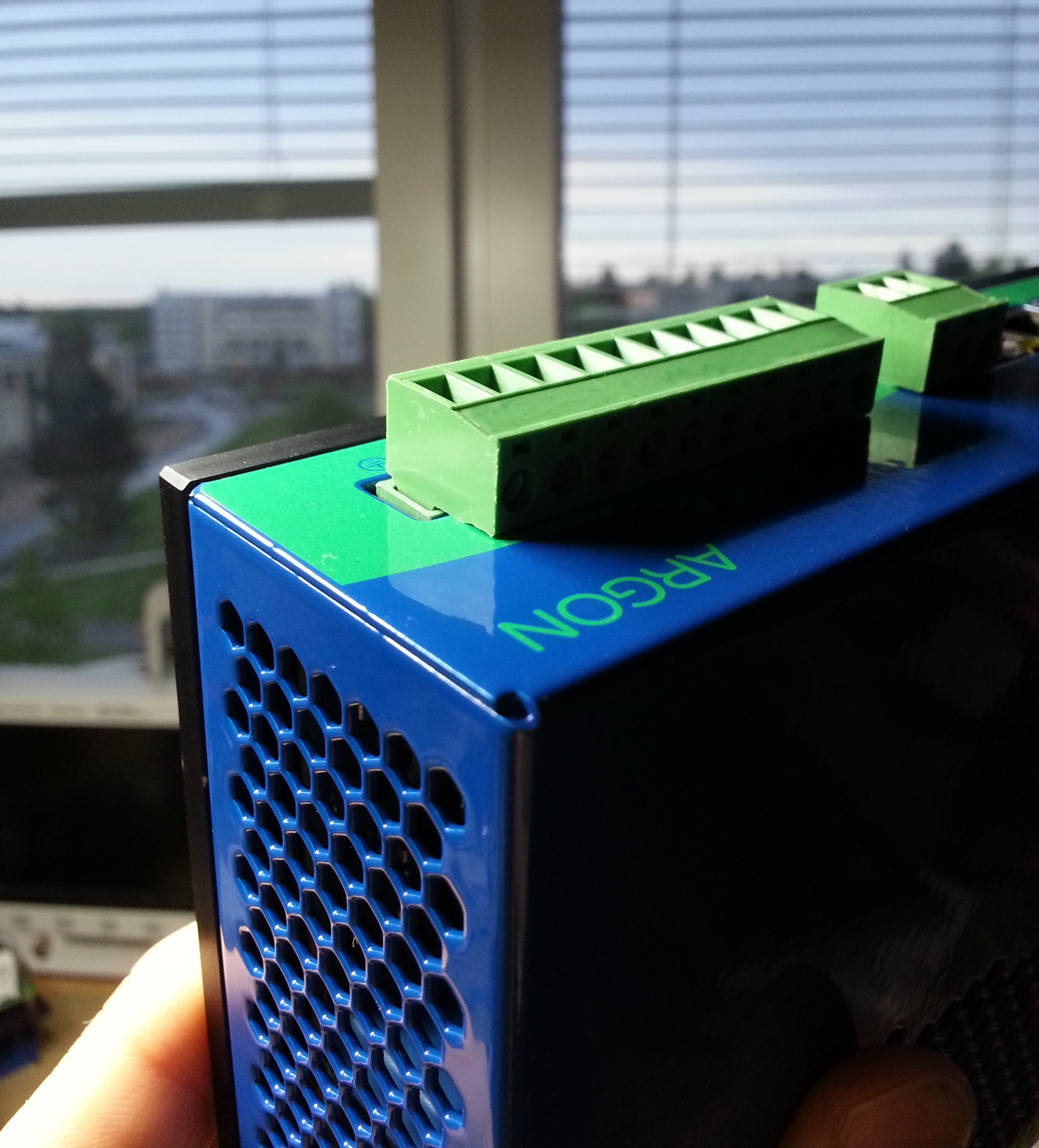
Argon final enclosure corner detail. Notice also hexagon shaped vent holes for minimal air flow resistance.

As Argon may be used for wide power range from 50 W to 1500 W, the cooling requirements will vary. To help high power users, we made mounting holes for standard low cost “half brick” heat sinks.

Enclosure heat sink side with additional heat sinks attached

Enclosure heat sink side with additional heat sinks attached

Tomorrow the enclosures will continue their journey to electronics assembly house where drive assembly will begin in just few days.

What to do with 1000 stickers?

The first attempt of making Argon machine labels was not successful. The labels are otherwise fine but the manufacturer didn’t notice the requirement of chemical resistance. CE compliance standard requires that label must withstand cleaning with isopropyl alcohol. Guess what happened to the text on these labels? You guessed it right – it becomes blank.

Argon machine labels, first try

Argon machine labels, first try

The second revision of labels have been ordered already. Any ideas what to do with a lots of obsolete stickers? :)

Status

Today we finished programming the Argon microcontrollers and sent them back to the assembly house. Production will start once all remaining components have arrived to the factory. We’re still waiting enclosures, should be less than a week away.

Chips being programmed in a clam shell socket

Chips being programmed in a clam shell socket. The chips are handled with a vacuum pen. The environment  is made ESD safe to prevent expensive errors.

Meanwhile I designed a testing procedure for the new kind of USB adapters that are produced same time with Argon drives. One SimpleMotion V2 USB adapter is necessary to configure drives and it may be also used to create PC based motion control applications for them.

SimpleMotion V2 USB adapter

SimpleMotion V2 USB adapter

The brains of Argon drives have arrived!

The microcontrollers used in the first batch of Argon drives have arrived for programming. We program these chips in house and send them to assembly house so we don’t need to make an needle bed type programming device to program mounted chips. So drives become functional right after assembly will be ready for quality control & compliance testing.

400 pcs of microcontrollers for Argons

400 pcs of microcontrollers for Argons in moisture barrier packages. The black item is a tray for 160 chips (same kind trays inside packages).

The chips will be programmed by using clam shell type IC sockets. Programming one chip takes about 5 seconds + handling.

Bare chip programming devices

Bare chip programming devices

Resetting STM32 option bytes

Without too much thinking I wrote a code to Argon’s STM32 ARM processor that write protects its flash content. After a minute I encountered a problem that I was unable to program anything new to the chip as it protects writing into memory also with a debugging tool effectively bricking the device. It took an hour to figure out how to restore the chip option bytes that determine if the flash memory is protected or not. JLink’s small utility that is supposed to restore STM32 option bytes didn’t appear to work for write protection so alternative solution was necessary to avoid replacing the chip on PCB.

After some googling (found this useful forum post) and reading chip data sheets I figured out how to do it manually with JLink Commander tool. I’m posting JLink command list here as I’m sure there are people needing this info, too.

(unprotect option bytes)
w4 0x40023c08,0x08192A3B
g
halt
w4 0x40023c08,0x4C5D6E7F
g
halt

(restore non-write protected state. one could also reset other option bytes here such as read protection or brown out reset settings by modifying the next line)

w2 0x40023C16,0xffff
g
halt

(write option bytes)
w1 0x40023C14,0xef
g
halt

I’m not sure if g and halt commands are necessary but used them just in case. This should work at least with STM32F2 series and probably also STM32F3 and STM32F4 chips too.

JLink Commander when unlocking STM32F2 write protection

JLink Commander screenshot after unlocking STM32F2 write protection