
Fighting with overvoltage or undervoltage faults when using servo drive? A newly written wiki page describes common reasons and how to solve the problem.
Let me know in the comments if you found this helpful, or if you would need further countermeasures!
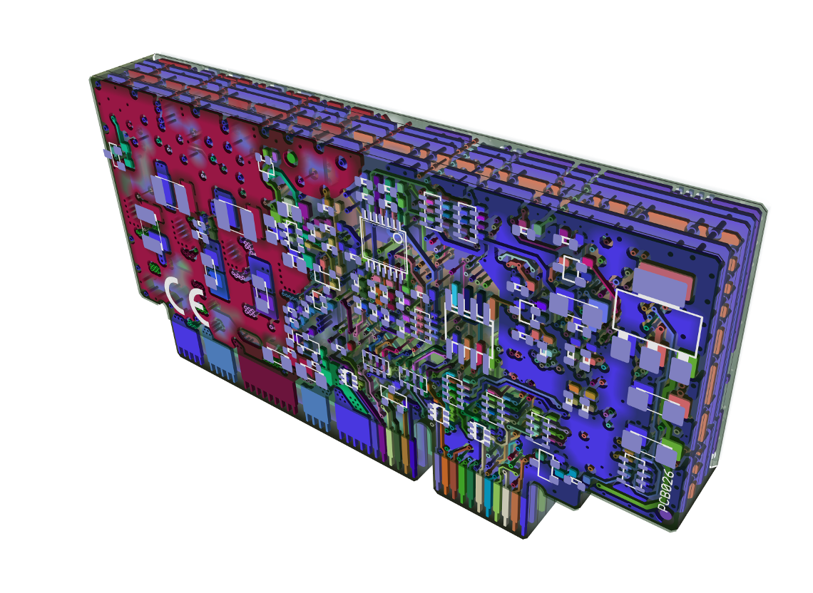
Offtopic image: IONI PCB in exploded 3D view (made with ZofzPCB)
Hi, I am not sure where to post this, so here it goes:
On the user manual page:
I see this:
5 B- Differential input B- Analog input B+
6 B+ Differential input B+ Analog input B-
It looks like the analog voltages are swapped. Is that a typo?
Indeed! It was typo, fixed now. Thanks for pointing out!
Also, I am trying to get my brand new IONICUBE 1X to work with my linear motor and am having a strange issue:
Background info:
I have a linear motor with pole pair spacing of 60.96 mm
The encoder is a 1 um/div linear encoder
AXT is set to Linear[mm]
AXS is set to 60.96 (cosmetic bug in granity thinks that is still in ‘mm per revolution’ even though this is a linear motor)
FBR is set to 60960 (again cosmetic error. This is PPR, but should be PP[mm] or something) (The wiki page says that values of 50000 may need a new firmware. Is that still the case?)
The pole pair spacing and encoder resolution are correct, as they work fine in another servo drive.
What works:
The motor generally responds to stimulus in position mode just fine.
A stimulus of 0-16000 moves the motor 16mm, as it should.
Tuning and responses all good as long as I stay in the 16000 count window. I can make it move snappier or slower by changing the tuning parameters.
What does not work:
as I try to farther than about 18000 the motor will not follow, and the tracking error will cause the drive to fault.
In granity, the ‘test stimulus generation’ pane thinks that 16000 = 4 mm. I don’t know if this is just cosmetic or an indication of what went wrong.
Any idea of what I set up wrong?
I guess you have seen this:
http://granitedevices.com/wiki/Configuring_linear_servo_motor
I updated that page, which should answer your questions :) Please check it again.
Also thanks for pointing out Granity cosmetic bugs. We’ll check them as well.
You immediately recognized the problem!
Thanks for updating that wiki page and responding to me so fast!!!
Checked the cosmetic bug: it’s “feature” rather than bug. Granity always assumes that we’re setting up rotary motor and when choosing linear axis, it assumes it’s driven by rotary motor. With direct linear motors, just imagine “pole pair” in place of “revolution” :)
I understand, and it was not a source of confusion for me. But for novices some hint might be nice. Not sure how to improve that short of putting ‘linear motor’ in axis type and then changing the units accordingly….
Ok, I am having one more issue.
The motor is tuned and works well. I am using an IONICube 1x.
Now it is time to get it moving with a pulse train. I set up pulse train and direction in goals. In the testing tab, I can verify that the HSIN2 toggles. However, the motor does not move; the setpoint value remains at 0.
Any ideas of what I am missing?
Step input should be HSIN1 not 2. Try swapping them and see if it helps!
Thank you!
In that case I think there may be another typo on the pinout of the x4 connector:
http://granitedevices.com/wiki/IONI_%26_IONICUBE_user_guide/Wiring_overview_with_IONICUBE_1X
HSIN2 Depending on setpoint mode, can be either: pulse input (of pulse/dir), PWM input or quadrature B input
HSIN1 Depending on setpoint mode, can be either: direction input (of pulse/dir or PWM) or quadrature A input
Just tested. HSIN1 is in deed step.
Thanks for pointing out! That error was also in other pages (fixed earlier), but that table was missed. It’s fixed now :)
I think I found another typo.
On this page:
http://granitedevices.com/wiki/IONICUBE_1X_electrical_specifications
the typical input requirement exceeds the maximum.
Related to that, it is not clear to me what happens to the 24V supply. Some is clearly regulated to 5V for encoder and such right on the IONICUBE 1X. How is the 24V logic turned to something that IONI can use? Regulator on the IONI board?
Indeed, it’s fixed now. Thanks!
Yes, there is on-board 24V to 5V regulator for encoder and IONI.
Ah, I see that cute RECOM switcher. I have a question:
I have been running my experiments with a bench power supply at 24V going to both HV and logic. If my final machine is at 24V, is that a good practice, or should I put a separate 24V SMPS to supply the logic voltage?
I have another potential bug report. I have tested this on two separate linear motors of different manufacture. When I go and do the hard homing and set the HMF movement to 0, so that the motor stops at the homing position, it goes crazy and starts pulling over 1A of current trying to hold it there. If I simulate a hard stop with my finger or set a move away from the hard stop (even a few microns), then there is no problem.
This happens because hard stop home point happens on or little bit beyond the end of travel, so when home point is set there, drive will try to drive axis towards the end of travel. The correct solution for this is to set homing offset parameter so that it moves away from the hard stop.
Indeed this is bit unintuitive behavior and I have put it on the TODO list to change it.
BTW, sorry for long delay on answer! I was not following this for a while due to travel etc. Your feedback is very welcome and I appreciate!
And if you are not sick of me just yet, I have one more thing to report:
in the testing tab of Granity, the TSP fields are limited to 99999. I have a linear motor with 1/2 micron glass scale here, so that limits me to <50 mm moving. Would be nice if that field could be increased in size, because I do have some other linear actuators here with 50 nm resolution….:P
That’s good point! In the next version TSP will have 10x range.
I can also confirm that IONI works on a Parker MX80L linear motor with sin/cos feedback.
However, in this case, the issue of the field sizes in Granity is a real problem. Aside from the stimulus issue I already reported, several other things just won’t work well.
The velocity field limits me to 32767. So even with the SinCos setting at only 64X, the max velocity is 128 mm/s. The motor is rated up to 2000mm/s….
I suspect similar issues with other fields as well.
Am I doing something wrong?
To overcome this, you need to reduce DIV parameter value which sets the scale of velocity/acceleration limits. I.e. if you change DIV from 100 to 10, you will get 10 times more range in velocity limit. Also change MUL if you wish to keep the setpoint scaling.
I’ll put a note about this somewhere in the wiki :)