EMC test have begun!

A day in a EMC lab yielded over 40 radiated emission measurements and lots of useful data about how to install the device to minimize interference.

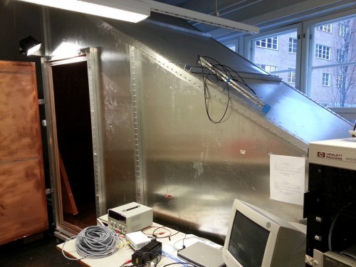
GTEM type EMC chamber

GTEM type EMC chamber

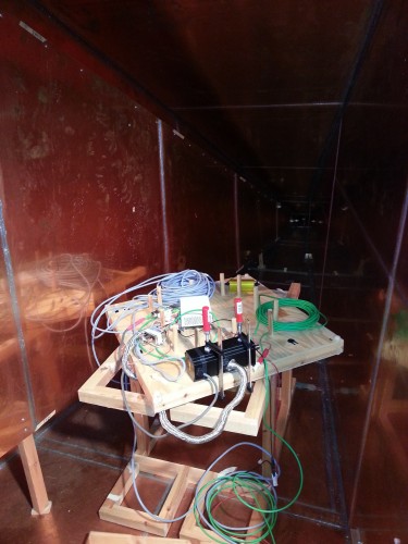
Inside GEMT type EMC chamber

Inside the chamber

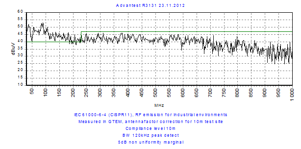
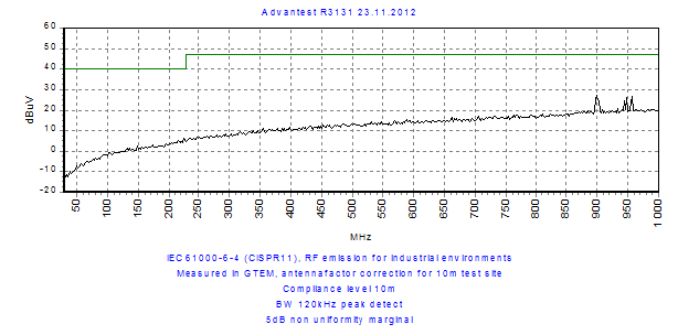
Few radiated emission test results shown below. The green line represents the limit to meet IEC 61000-6-4 limits in industrial environments, so any spike above it would mean that device is not compliant.
Chamber & measurement equipment bacground noise

Chamber & measurement equipment background noise. The small spikes in GSM frequencies can be seen beyond 900 MHz. Notice that graph has different scale than the ones below.

These tests were carried out while drive was executing 10 Hz high current square wave torque command which was found to produce the worst case scenario.

Driving square wave torque command without any added filters on cabling

Driving square wave torque command without any added filters on cabling

By experimenting we found out that a ferrite bead core on 3-phase output leads (as common mode filter) before motor cable makes a quite significant difference. The graph below shows a success in emission test. This test was repeated several times in different ways to eliminate the possibility of error.
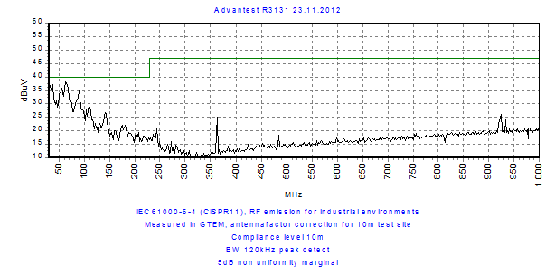
Driving square wave torque command with a ferrite bead filter on phase leads

Same as above but with a ferrite bead filter on phase leads. A spike visible at 360 MHz is probably a third harmonic from the 120 MHz CPU.

In addition to emission tests, also radiation immunity test was carried out. No sign of disturbance was noticed on drive operation or communication to PC, so immunity test was passed as well.

Next up: ESD & EFT tests. But first I’m going to visit Germany and SPS IPC DRIVES fair in Nuremberg. See you there!

Preparing for EMC testing

Tomorrow will be a big day for Argon; it will be tested for EMC (electromagnetic compatibility) standards in a test laboratory. The tests consists several measurements: radiated emissions, conducted emissions, radiated interference survival, electrostatic discharge and surge current tests.

Argon will be tested against the most stringent standards that the CE regulations specify ensuring (if passed) that it may be installed in virtually every environment without violating the regulations. For example different cable length classes exists. Some classes require testing up to 3 meter cables but I chose to use the class that requires passing all tests with 30 meter cables in addition to 1 meter cables. In some cases 1 m cables may give worse results so testing with a such short cables is also a requirement.

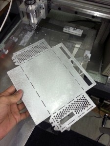
Milled enclosure sheet metal

Milled enclosure sheet metal

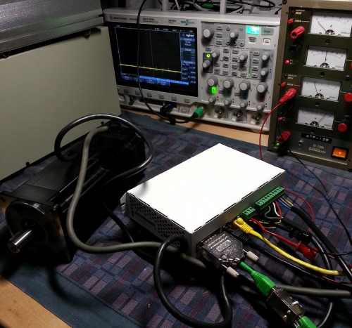
The device under test has a self rolled enclosure milled with a self made JV2 CNC router. The sole purpose of this prototype is to check fitting and provide EMI shielding during the tests. The final enclosure will have more professional finish.

Argon testing with work-in-progress enclosure

Argon testing with work-in-progress enclosure

About that feedback device port

The feedback device port of Argon has “only” 15 pins, just like earlier drive model VSD-E, but tons of more of more capabilities have been squished into it. It has:

  • 5V 500 mA output
  • 5 differential input lines where 3 of them are bidirectional
  • 3 single-ended digital inputs
  • 2 differential 1 Vpp analog inputs
  • Differential inputs may be used with single ended signals as well

All this makes it possible to support many kinds of feedback devices such as:

  • Quadrature encoder with index channel
  • SinCos encoder with interpolation factor up to 1000x
  • Tachometer
  • Resolver (a.k.a. synchro)
  • Hall sensors
  • Serial encoderes (SSI, BISS etc). Support for example for Austria microsystems low cost magnetic linear & rotary encoders possible.

VSD-E could support only the first of them so I think the progress is quite significant.

What’s on board?

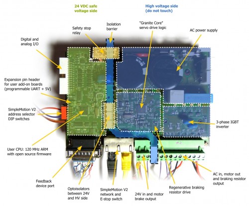
Describing it all on text would be too long and confusing, so I made a picture.

Argon functional internal layout

Argon functional internal layout

I’m sure questions will arise, so feel free to ask in comments!

Sneak peek to Granity servo tuning software

One of most important parts of the project is the Argon configuration tool Granity. The tool was originally named as GDtool 3 but that name was ditched as the software has been completely redesigned & rewritten – no single line of the old code has been spared.

 “Make everything as simple as possible, but not simpler” – Albert Einstein

The main focus during design of Granity is to eliminate confusing parameters and make it harder to use it wrong. I.e. the software will notify user if one forgets to click Apply button before doing step response tests. Also the parameters causing most confusion in GDtool 2.x are replaced by more understandable ones.

Surprisingly, simplifying the usage also simplified the source code. GDtool 2.5 consists 15 800 lines of code while Granity consists only 6 500. I call that progress!

Short circuits

Argon has pretty sophisticated circuit protection functionality. The device has sub-microsecond response short circuit sensing circuit that can detect phase-to-phase and phase-to-ground shorts. To counter harsh environment EMI and prevent false fault triggering, there is variable length digital delay filter for short circuit protection  – and this parameter is also user adjustable.

SC scoping

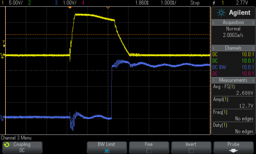
Short circuit scoping. Yellow trace is IGBT phase current 67 A/div and blue is power stage shutdown signal from DSP.

The oscillograph above displays a phase-to-ground short circuit when shorted by a piece of wire right at output terminals. Drive was driving an AC motor at supply voltage of > 200 VDC while wire is shorted to ground. The yellow output current graph shows current of 170 Amperes and pulse length of about 2 µs before shutdown was issued. I believe the blue digital trace is fluctuating because board’s ground plane is struggling to carry the enormous current.

The test has been repeated dozens of times with varying protection delay times and supply voltages, and no harm to hardware was ever induced. I’m satisfied.

Industrially made Argon boards

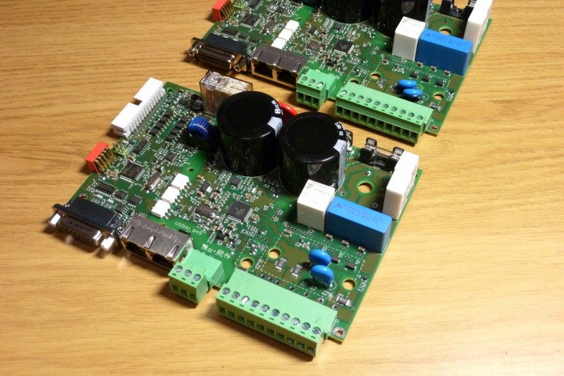
Last week I received first industrially made Argon circuit board assemblies from the factory. It’s pretty amazing feeling when more than a year of design work is finally shining on your desk.

Argon PCBA

Argon circuit board assemblies, first batch of release candidate boards

The boards came without bottom side power components mounted because I had mistakenly specified wrong size bridge rectifier to the BOM. Its height supposed to be 8 mm but factory reported that their parts have 11 mm height. That would make fitting to the enclosure pretty difficult. So I told them to supply bottom side parts unmounted as its no problem to solder them to place in here.

First post!

Welcome to my very first blog! A year ago I would never have believed to ever become a blogger, but now I am.

This blog has been dedicated for my enthusiasm towards electronics, robotics and, most importantly for my greatest achievement, industrial grade motor drives.