IONIs are here!

No words needed, but I write anyways! Today is the day when first production candidate IONI drives arrived. Few minutes after arrival, the first motor was spinning with great success.

The production candidate IONI drives

The production candidate IONI drives

So far everything is looking very good. Someone please come and tie me to the chair so I can stop floating around!

SimpleMotion v2 bus termiantor/breakout board eases setup

As the multi-drop bus, SimpleMotion V2, contains also dedicated signals for drive Enable and Safe torque off, there is need for user to make electrical wiring to the bus. Based on support requests and feedback, we figured out there is need to ease this job. This is why SMV2BRK (SimpleMotion V2 break-out-board) was created.

SMV2USB adapter and SMV2BRK bus termination board.

SMV2USB adapter and SMV2BRK bus termination board.

Typical SimpleMotion V2 bus with SMV2USB and SMV2BRK.

Typical SimpleMotion V2 bus with SMV2USB and SMV2BRK.

Wiring of Enable and Safe torque off switches to SMV2BRK.

Wiring of Enable and Safe torque off switches to SMV2BRK.

SMV2BRK will become available through the web shop shortly. SMV2USB and SMV2BRK will be also sold as kit.

IONI hardware design ready and sent to production!

This week we have reached the point where we could no more improve the hardware design of IONI. We celebrate this today by placing the first release candidate batch (10 pcs) of IONIs in production. Factory quoted lead time is 4 weeks from the order.

IONI see-thru image

IONI see-thru image in autumn colors. The final board is size is is 69.5 x 36.5 x 6.5 mm.

Meanwhile firmware will be finished so volume production should be able to start right away from prototypes are received and tested. Also production of IONOSPHERE will be begun at the same time with drives.

It’s called IONOSPHERE

The proto PCB’s of ION motherboard have arrived! Boards are just waiting for assembly to let us begin testing.

IONOSPHERE four axis motherboard and ION drives awaiting assembly.

The IONOSPHERE four axis motherboard. The design shares VSD-E’s benefit of having motor and encoder connectors on same face so it can be easily installed through a panel.

This is the ION motherboard!

Despite of being quiet, we have not been resting all summer. The four axis motherboard for ION drive is only pending “proofreading” and last minute ideas before prototyping.

The solution here is to use PCI-express 8X connectors where extra pins may be used later for higher power drive. The first ION model has PCI-e 4X connector and plugs in 8X socket too.

ION motherboard design nearly ready for prototyping

ION motherboard design nearly ready for prototyping

The board has been designed to be ideal solution for CNC, 3D printing and custom motion control systems. Key features include:

  • Carry up to 4 ION drives
  • On-board regenerative braking resistor
  • Each axis can have mechanical end switches and homing switch
  • Motor holding brake drivers for each axis
  • The first 26 pin ribbon cable connector is laid out so that it’s directly connectible to traditional CNC controllers (parallel port, SmoothStepper etc).
  • The second 26 pin connector has extra I/O for drives and analog setpoint inputs for custom applications
  • No separate break-out-boards needed
  • Charge-pump input for safety
  • E-stop switch input (safe torque off)
  • PWM to 0-10V converter for VFD spindle
  • Two relay drivers
  • Argon compatible encoder connector pin-out
  • RJ45 connectors for SimpleMotion V2 usage and configuration
  • Address selector jumper: up to 4 boards can be chained in one SMV2 bus (total 16 axis)

Any further ideas welcome! There’s still time to add more in it :)

New poll (DIY board assembly)

Printed Circuit Board Through-Hole Assembly.

Printed Circuit Board Through-Hole Assembly.

We’re in progress of designing an open source accessory circuit boards for ION drive that are sold as finished product but instead they are DIY. So we will provide the design files (PCB & schematics) and maybe sell bare PCB’s too but assembly (soldering of components) should be done by user.

The poll is there to study which kind of PCB assembly skills people do have. Through hole components are easiest to assemble but is it necessary? Or do you prefer surface mount components (SMT) which would yields smaller PCB size? Vote and share your thoughts in comments below :)

SMT assembly

SMT assembly

How high dynamic range torque control works?

Motor coil current sensing is one of the most critical component in a well behaving motor drive. This is true because current readout data is being used as feedback signal for closed loop torque controller as motor torque is directly proportional to coil currents. The importance of good torque control can be understood by knowing the fact that the the final step in drive’s signal path is always a torque controller. This means, any error in current sensing will eventually reflect to motor shaft, no matter which control mode is being used.

Today’s big achievement was the implementation of adaptive current sensing for high dynamic range torque control (HDRT) for ION drive. The captures below reveal the inner workings of this technology.

Illustration of measured current signals from ION. Each phase current is measured twice: with high sensitivity and low sensitivity. The high sensitivity signal has higher current precision but is limited to about +/-3.5A range. The low sensitivity signal has range of +/-23A but comes with less precision. The drive combines these two signals into one by making it both accurate and high dynamic range.

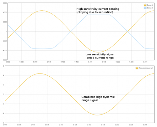
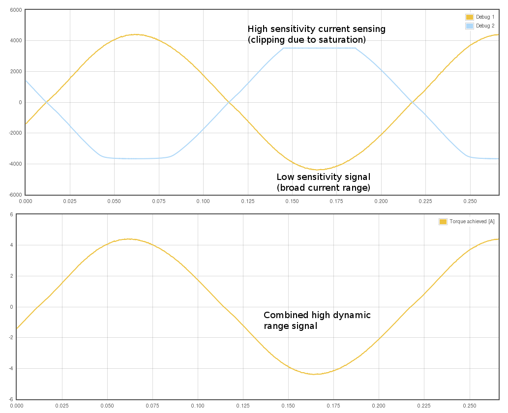
Illustration of measured current signals from ION. Each phase current is measured in two channels: with high sensitivity and low sensitivity. The high sensitivity signal has higher precision but is limited to about +/-3.5A range. The low sensitivity signal has range of +/-23A but comes with less precision. The drive combines these two signals into one by making it both precise and high dynamic range.

Zoomed image of the combined high dynamic range current sense signal. The switch between high and low sensitivity happens at 2.5A. As seen from the image, the curve above 2.5A is little bit more rough than below 2.5A.

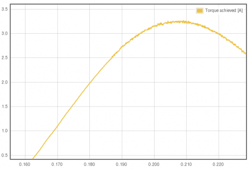
Zoomed image of the combined current sense signal. The switch between high and low sensitivity happens at 2.5A. As seen from the image, the curve above 2.5A is bit more rough than below 2.5A.

One major motivator behind HDRT is to expand the range of motors that can be driven with single drive without exhibiting any of the typical drawbacks that come when a small motor is being driven with a large drive (motor hiss, jitter, torque ripple, position hunting). It also gives maximum precision for those who want the best performance in torque control mode.

Both ION and ARGON utilize low noise 12 bit analog-to-digital converters (ADC) and discrete Op-Amps for acquiring the sensor signals yielding the effective current sense precision of 14 to 15 bits. Most of the drives I’ve examined use a single sensing range and a 10 bit ADC. That is a significant enough difference to be seen, heard and felt by anyone :)

ION development status & further plans

Just a quick update of ION servo drive development: all hardware peripherals are now programmed and functioning properly and all hardware “typos” are corrected in the schematics & PCB layout. This is important milestone as now we can preparing the first production batch of hardware even when firmware is not fully complete. Firmware development will continue on prototype while we wait hardware from fabrication.

Meanwhile, I have been pondering how to make the higher power version of ION. Some options are:

  • ION with 84 pin card edge connector (now 64 pin) and larger power stage. This can yield approx 10 A 90 VDC capability (limited by card edge connector).
  • Add external power connector to ION. This eliminates card edge connector current & voltage but might would look weird and impractical. Also fitting large power stage on the board could be difficult.
  • Get rid of card edge connector and replace all with wire terminals. This would easily give highest voltage & current rating but would not get benefit of ION motherboards, so wiring work would increase significantly. This option would look like updated VSD-E.

Which one sounds preferable to you? Leave a reply in comments :)

Something completely different – Laser diode driver!

Along motor controllers, we have been designing a laser diode driver. Laser diode driver, or LDD, is basically a current regulator that is used to drive constant or pulsed current to a semiconductor diode that emits laser light.

Intensify Nx50 laser diode driver delivers continuous current of 50 A at exceptional 95% efficiency.

Intensify Nx50 laser diode driver delivers continuous current of 50 A at exceptional 95% efficiency.

The story behind this is the fact that I have been working close to laser diode industry where I get understanding of how laser diodes are utilized and controlled, as well as expertise of precision current control from motor drives. Combining these two makes it almost trivial to make a new kind of LDD that has never seen before.

Intenisify Nx50 laser diode driver delivers up to 150 A continuous current when three boards are connected parallel by stacking

Three Nx50’s stacked forming a 0 – 150 A driver.

The product is now finished and it’s called Intensify Nx50. It has unique ability to be stacked to increase output rating. Single board outputs current between 0 – 50 A and voltage between 0.8 – 5.0 V. Two of them output 0 – 100 A / 0.8 – 5.0 V and three 0 -150 / A 0.8 – 5.0 V etc.

Funny observation from testing of 150 A driver in pulsed mode is that the thick cables tend to physically move due to magnetic force generated by flowing current. When current flows in parallel conductors in opposite directions, cables repel each other. It takes hefty amount of current to feel and see it :)

ION development progress

ION development has been very active in the last 2 weeks. Last achievements are the implementation of ADC readouts and power stage control. Both were discovered to have some schematics & layout errors, but that’s why people make prototypes.

Ion development rig as it exists today

Ion development rig as it exists today. Tiny jump wires on ION board have appeared.

After fixing the issues by PCB trace cuts and jump wires, the drive seems fully healthy. ADC readout of phase currents seems to perform well with extremely low noise and power stage seems to exceed the initial capability calculations. At the moment power stage temperature is 63 degrees Celsius while it outputs 8 A continuous current to the stepper. Some air flow is present from the fan behind the motor.