Testing app almost done

Testing procedure of Argon drives is ~80% done now. The testing system consists of:

  • Hi-pot tester which verifies insulations at 1.5 kV AC voltage
  • Testing hardware (artificial test load, various I/O testers, etc)
  • Testing software for the above hardware
  • Test functionality in firmware

The testing software is based on Granity with some modifications.
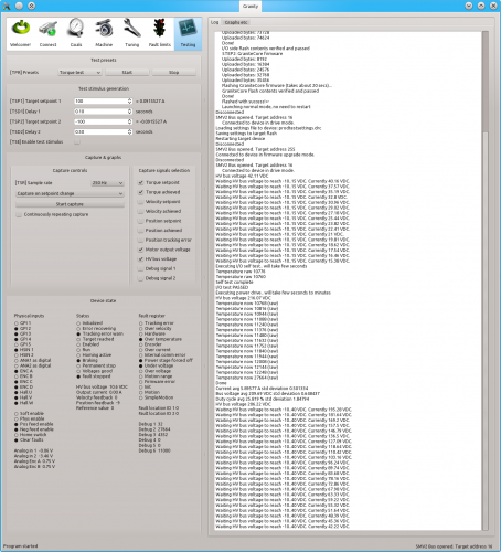
Argon testing application work in progress

Argon testing application work in progress. Most of the UI stuff will be ripped off from the polished testing version and instead provide only a simple “start test” button to eliminate human error.

I will start testing the first drives as soon as the test software fulfills it’s all technical requirements and bring first drives to market ASAP. Polishing the software for assembly house can wait couple of weeks as it will affect only next production batches.

Only testing routine to go!

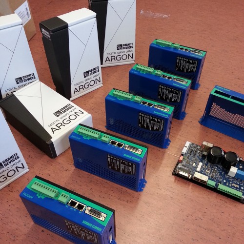
More Argon drives have arrived. Mandatory parts of lab tests with the new hardware are done and everything is looking good hardware point of view!

More Argon drives

More Argon drives

The only thing remaining before the drives are placed on sale & ready for shipment is finalization of the testing routine. As mentioned in earlier posts, every aspect of the drives must be verified before they’re good to go. Nothing is left on chance.

Amounts of items returned is not just a number for us. We take testing & quality very seriously because we don’t want (and don’t have) many returns due to defects. Having >99% yield helps to save our time and also leads to reduced cost to customer. I think it’s also nice to buy hardware you can count on :)

Status

Today we finished programming the Argon microcontrollers and sent them back to the assembly house. Production will start once all remaining components have arrived to the factory. We’re still waiting enclosures, should be less than a week away.

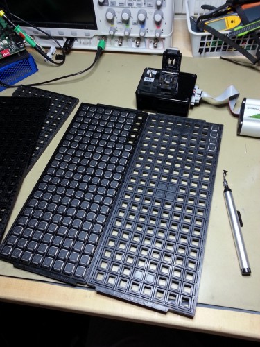
Chips being programmed in a clam shell socket

Chips being programmed in a clam shell socket. The chips are handled with a vacuum pen. The environment  is made ESD safe to prevent expensive errors.

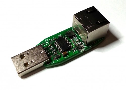
Meanwhile I designed a testing procedure for the new kind of USB adapters that are produced same time with Argon drives. One SimpleMotion V2 USB adapter is necessary to configure drives and it may be also used to create PC based motion control applications for them.

SimpleMotion V2 USB adapter

SimpleMotion V2 USB adapter

Finding power limits, part 2

Long time since last tech related post! Today continued the test to find Argon drive power limits (see earlier tests here). This time I loaded drive’s internal AC to DC power supply with an old room heater while simultaneously measuring transmitted power from AC and DC lines.

The heater pulled 1.53 kW from drive HV DC bus for about 45 minutes continuously with only passive cooling of the drive. Temperatures were measured from multiple points of drive along PSU current path (components & PCB traces) to find out if anything is overheating. I’m happy to report that everything stayed relatively cool which means the drive is capable of at least 1.5 kW output continuously! The hottests parts inside were 8 Amp fuses which is easily helped by using larger fuses.

2 days left!

There’s still plenty of time to submit your idea to the box competition. Currently submitter’s chances of winning are good as no huge flood of submits (at least yet!) have been recorded.

Meanwhile the other news in Argon project:

  • I have been mostly designing the routine test for the factory making Argons. This needs quite careful thinking because as usual, everything must be tested. No single I/O pin or internal circuit feature shall pass without being verified to be good.
  • Also the design for USB SimpleMotion V2 adapter that is needed to communicate with Argons have been finalized and placed in production

Safety checking results

Today I got first results from the accredited testing service for compliance of power drive safety standard EN 61800-5-1. They did good job and found few issues:

  1. Isolating transformer between user touchable and hazardous voltage side doesn’t meet reinforced isolation requirements
  2. Clearance from power stage & bridge rectifier mounting screws to PCB tracks not large enough
  3. On one side of the enclosure the vent holes are too large to meet IP30
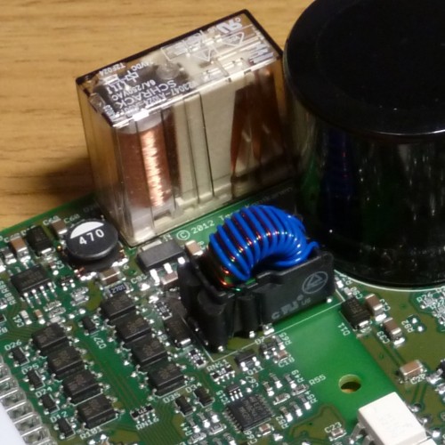
Isolating transformer (blue) has 3 kV isolation spec

Logic power isolating transformer (blue) has 3 kV isolation spec but still doesn’t meet the strictest interpretation of  the safety standard

Luckily none of them is hard to fix but finding them early was very important!

Update

By contacting transformer manufacturer we learned that the blue winding consists triple insulated teflon wire which fulfills the reinforced isolation standards. If we can confirm that, we save few days of isolated PSU circuit redesign & testing!

Finding drive power limits

Lately I have been concentrating on finding the current & power limits of the Argon drive. I have used the artificial load unit as test load.

Testing has gone well and has revealed things I didn’t know about Argon. The most positive surprise is that the drive seems to be able to deliver a lot more continuous power than calculated. The first anticipated limiting factor in the design was the equivalent series resistance (ESR) of the bulk capacitors. ESR sets the limit to the maximum ripple current that AC-to-DC power supply can handle because current flowing through capacitor’s internal resistance will heat them up and eventually make them reach their maximum safe temperature.

By calculating maximum ripple current & power based on capacitor specs I came up with figure of 700W continuous power before capacitors get too hot (105⁰C). However, by testing I found out that even at 1200W continuous output the caps didn’t get warmer than 37⁰C. I think capacitors either are way better than specified or their ESR is specified at 105⁰C which may be much higher than the ESR in room temperature. So 700W is probably the limit when capacitors already run hot (needs very high ambient temperature) and at least 1.2kW may be extracted at room temperature.

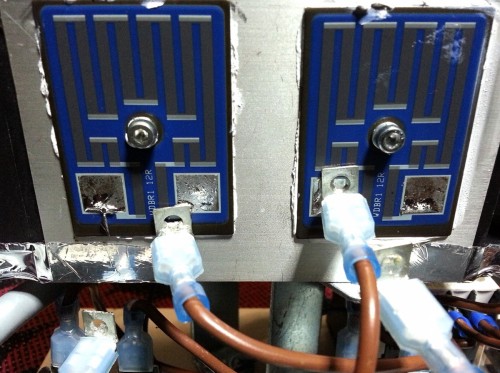
Power resistor fused open as terminals desoldered them selves

Oops! Artificial load unit power resistor wire terminals desoldered them selves under little bit too much pressure

Feels very solid

We finally have received the samples of enclosure consisting steel sheet metal cover and aluminum heat sink plates. So the front panel art comes with trees as voted best in the previous posts. My thanks to everyone giving comments to that post! It really helped us to make the best choice.

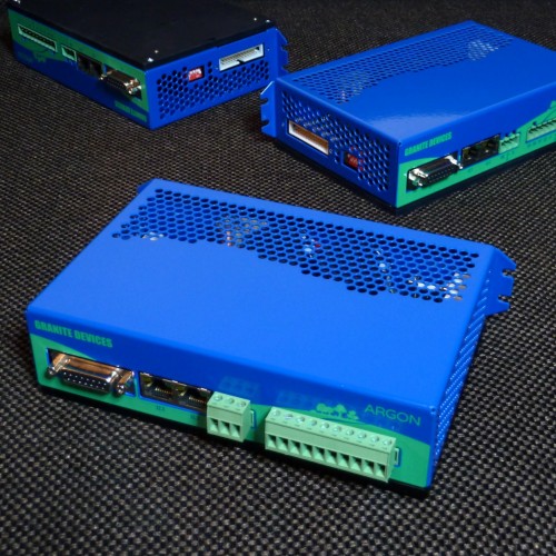
Argon prototypes with industrially made covers

Argon prototypes with industrially made covers. LED numbering texts (above the RJ45 sockets) were mistakenly forgotten from the front panel art.

The cover slips on smoothly unlike the first self made prototype which required bending one side in order to install it on the device. The realized design looks and feels very solid and leaves only little space for improvement. However, few improvements will be carried out mainly to help assembly, most of them being related to threading for mounting screws and adding more accuracy to bends.

To the final design I’m also considering to add an placeholder hole for possible extension port that could be installed inside the drive as stack-on circuit board. Extension boards could be made by end users, third parties and of course by us.

Surviving lightning strikes

Today I went into the lab to repeat some surge tests that let the smoke out of Argon’s on-board voltage regulator the last time. This time some circuit modifications were made as attempts to enhance the surge voltage & current handling. Surge test attempts to emulate a lightning strike.

Total of 12 a bit different surge pulse tests cases had to be carried out to meet the EN 61000-6-2 and EN 61000-4-5 industry standards. In the list below are the open circuit voltage and series resistance that are shot to the target voltage supply lines:

  • + and – 500V 2Ω between 24V and 0V (DC supply)
  • + and – 500V 12Ω between  +24V input and chassis (DC supply)
  • + and – 500V 12Ω between 0V input and chassis (DC supply)
  • + and – 1000V 2Ω between L and N (AC input)
  • + and – 2000V 12Ω between L and chassis (AC input)
  • + and – 2000V 12Ω between N and chassis (AC input)

The surge tests are typically more difficult to pass than ESD & EFT due to high injected energy and currents. For instance 500V and 2Ω  produces current of 250A and 1000V 2Ω yields whopping 500 Amperes. That will heat up the overvoltage protectors quite extremely and weaker components simply explode.

Now all tests passed without damage and motor was servoing simultaneously through the whole test. Changes will be brought to the PCB design which makes a big step closer to the final design.

Artificial load

I hope our followers have had a restful Cristmas break and joyful beginning of the new year! Anyway, time to get back to the business.

The photo below shows the artificial load unit to be used in Argon production testing process. In other words it will be used to simulate heavy load for drive power stage electronics to separate the wheat from the chaff.

Artifial load unit

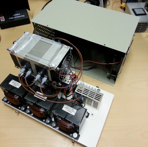
Artificial load (work in progress). The most of energy goes into the flat power resistors mounted on the sides of the heat sink block.

The unit consists of three inductors and three power resistors forming a 3 phase load that simulates a motor stator. In the same high density heat sink there is also a fourth power resistor that provides load for regenerative resistor IGBT switch.

Other stuff inside provides power for cooling fans and contactor that safely disconnects the load in case of over heating. The two fans in the heat sink are installed in push-pull configuration for maximum air flow.