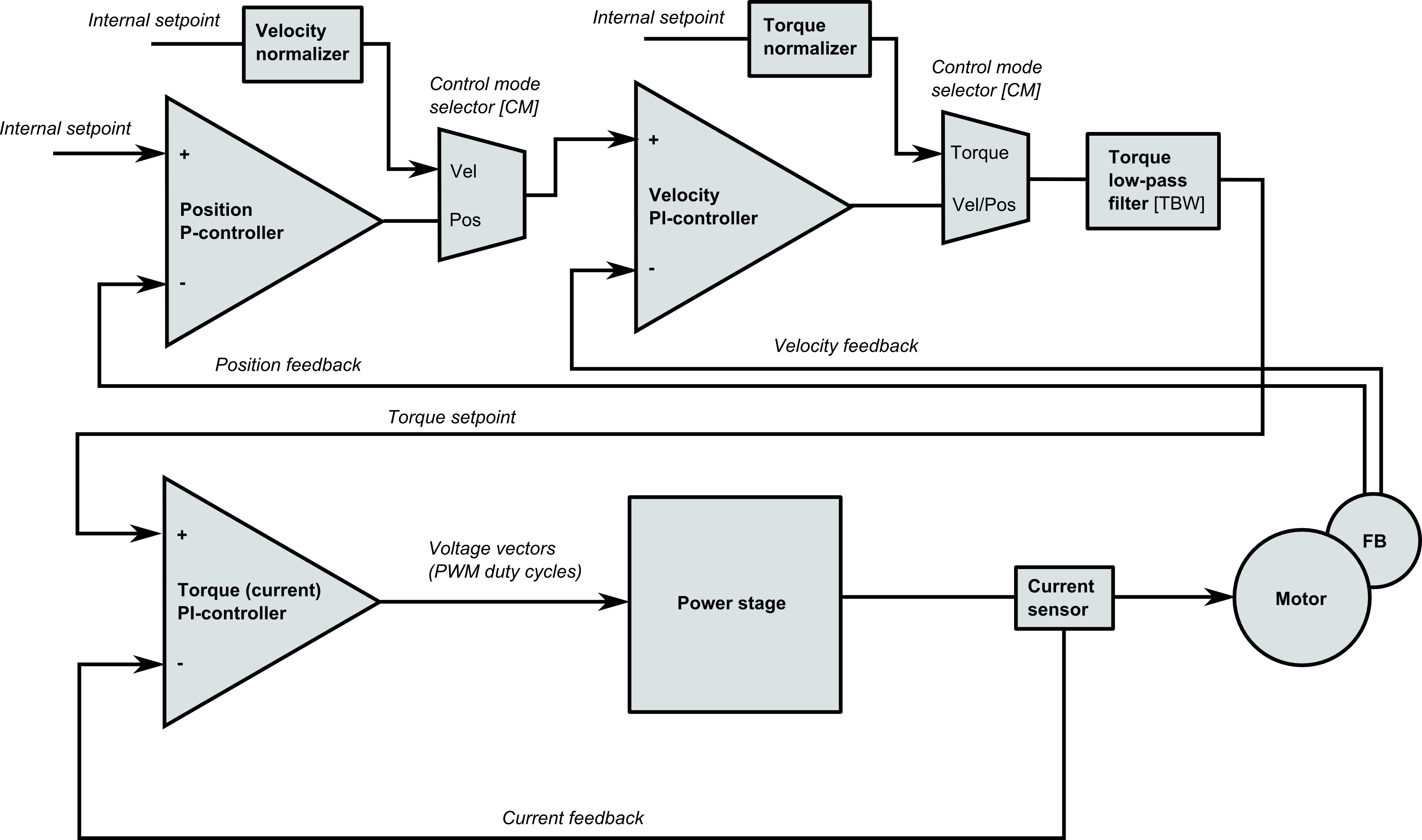
The latest achievement in IONI servo drive development was the maximization of torque control bandwidth. IONI actuates motor by a 20 kHz pulse width modulated (PWM) power output which essentially means switching the supply voltage between 0V and supply voltage (HV+) very fast causing the desired current to flow in the motor coils. Drive samples coil currents once at every PWM cycle and also re-calculates the PWM duty cycles on every cycle.
Last couple of we have spent perfecting the torque controller speed without sacrificing the dynamic range or smoothness. Bandwidth of controller is dictated by two factors: update rate and delay. Update rate was already at maximum (every cycle) but previously the delay was one full PWM cycle (50 µs). By optimizing code enough, drive is able to complete torque control calculations within half PWM cycle (<25 µs) which shortens the delay by 25 µs.
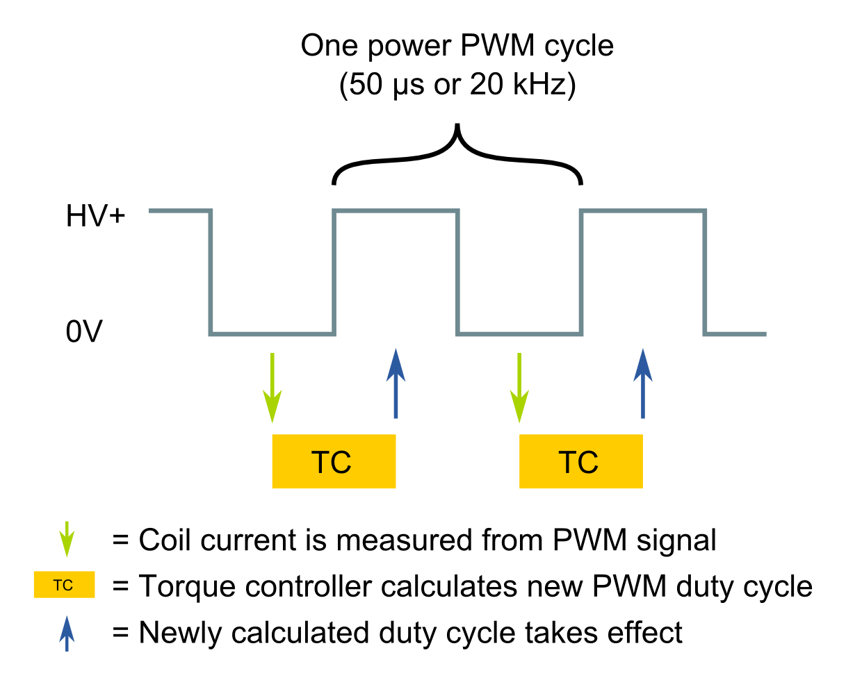
High bandwidth torque control timing diagram demonstrating half PWM cycle delay and full PWM frequency update rate. Torque controller has the highest bandwidth when the update rate is at the maximum and delay at the minimum.
Ok, 25 µs doesn’t sound much. But it actually is more notable than it first seems. This change yields 30-50% boost in torque control bandwidth which can be seen sharper change of torque without causing any overshoot. This allows us to set position and velocity control gains higher without losing stability. In the end, the result is more stable and more stiff servo motor.
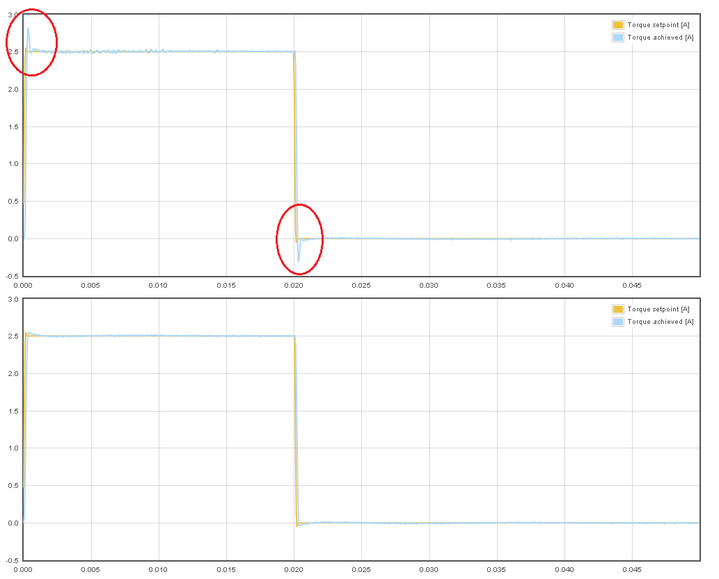
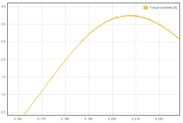
Torque controller step response with one PWM cycle torque control delay (top) and half PWM cycle delay (bot) without changing torque controller gains. Notice the overshoot caused by the additional delay. The overshoot can be cured by lowering torque control gains, but that also reduces bandwidth.
Never seen servo motor so stiff :)