For those who are interested to see how servo drive internals are constructed, see the new Wiki article: Signal path of servo motor drive. The diagrams presented in the article are useful when designing systems where servo drives are part of the system.
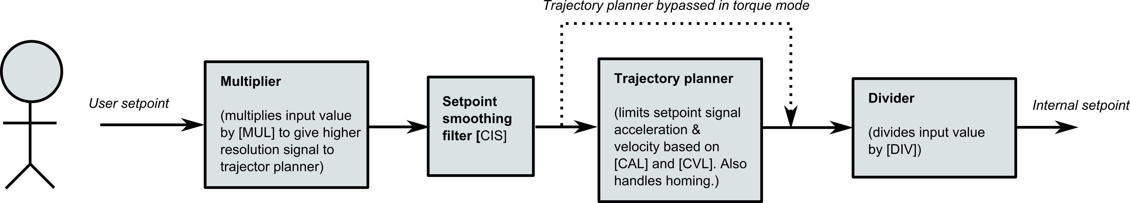
Signal path from setpoint source (user interface) to internal setpoint (fed to actual servo control)
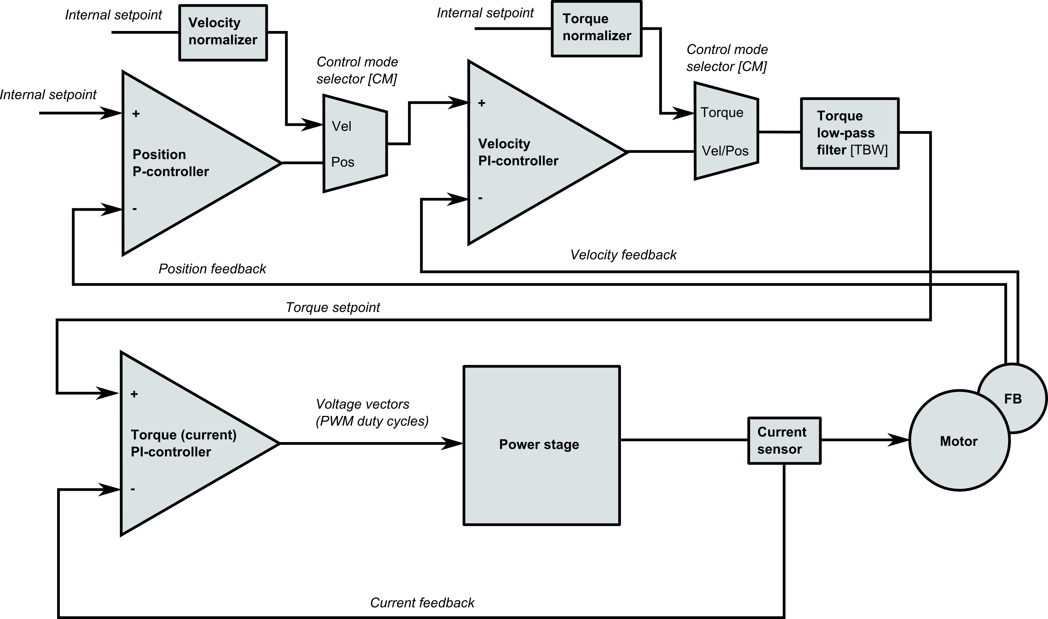
Drive block diagram that applies to all GD drives starting from VSD-E
The diagrams are also useful when designing custom code to Argon open source I/O side firmware. The I/O side microcontroller acts as provider of User setpoint as well as position and velocity feedbacks referred in the images. Rest of the illustrated logic lies inside the GraniteCore.