3-phase magic trick

Latest innovation made to IONI firmware allows generating 15% higher output voltage for 3 phase AC motors which in practice means 15% greater maximum possible speed of motor. This is achieved by by altering the duty cycle generation of power stage so that it’s being utilized better for this kind of waveforms.

By looking the typical 3-phase motor voltage waveforms below, one can notice the peaks of sine waves occur one-at-a-time which means there is some headroom in the opposing polarity waves.
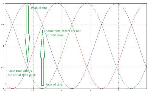
Standard 3 phase sinusoidal waveforms. Range from 1 to -1 means it uses full output voltage span available in drive (i.e. 0V to 50V).

Standard 3 phase sinusoidal waveforms. Range from 1 to -1 means it uses full output voltage span available in drive (i.e. 0V to 55V)

We can utilize these empty gaps by shifting all three waves up and down so that empty gaps become filled.
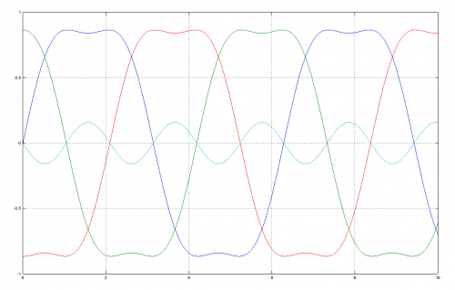
Same signals with summed third harmonic (cyan) to all phase values. This reduces peak amplitude of all signals by 16% without affecting to any phase-to-phase waveform shape or amplitude.

Same signals with summed third harmonic (cyan) to all phase values. This reduces peak amplitude of all signals by 15% without affecting to any phase-to-phase waveform shape or amplitude. In other words, motor sees no difference between this and the original.

After this step, we can multiply them by 1.15 without exceeding the maximum range of +/-1. This method has been tested and it works flawlessly. Same smoothness but just a bit higher speed range is available from the drive. The trick effectively does same as increasing drive supply voltage from 55 V to 64 V without actually increasing it.

This, and as many as possible, new features of IONI will be ported back to ARGON as soon as the IONI is out.

Adaptive current limit

We have been experimenting with adaptive current limit on IONI prototypes. This means there isn’t fixed specifications saying how much current drive outputs continuously and peak but there is just one specification: maximum. Drive will allow maximum output if it runs cool enough and will start throttling down current if temperature rises beyond certain level. This means, if you cool it well, you will get lots of power.

So far it seems to be working very nicely! See the video below.

As we were now able to push prototypes to their limits without worrying to break the only units, it turned out that we have been underestimating them! Without cooling it seems to output approx 9-10 Amps and with cooling 15 Amps (actually it could go higher but the lab power supply ran out of juice). What do you think about this?

Fanuc serial pulse coder support for Argon servo drive

As Fanuc servo motors are quite common target for drive retrofitting, it was tempting idea to make native support for their serial communication based encoder on Argon drive.

The protocol seems quite straightforward based on the details people have found out. So without much wasting time, I purchased a Fanuc motor and hooked it on the drive. Argon encoder port has total of three programmable RS422 inputs and two RS485 inputs/outputs which would make it possible to communicate with almost any kind of serial encoder.

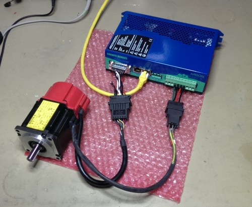
Fanuc servo motor with serial pulse code connected to Argon drive

Fanuc “red cap” servo motor with serial pulse code connected to Argon drive

Fanuc encoder outputs data in form of asynchronous serial communication that is transmitted and received by UART. During testing, it occurred to me that encoder outputs very unusual 76 bit word with single start and stop bit. Standard UART support 5 to 8 bit words so the internal UART of drive’s microcontroller will not help here. Implementing a custom 76 bit 1024 kbps serial receiver with bare software would be so tricky that plan of supporting Fanuc protocol is unfortunately looking quite improbable at the moment.

The working solutions for using a Fanuc motor are:

Most of serial encoder protocols (SSI, BiSS, etc) use SPI style transmission which is way easier to implement on software. Plan of supporting those is in the future plans, we just need some hardware and time to begin with.

The very first ION servo drive

Good news! The very first fully assembled ION servo drive boards have arrived. I jumped straight to programming the thing. Few parts of code have been already ported from Argon and everything has worked flawlessly so far.

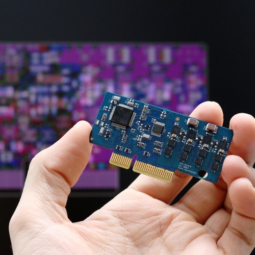
The very first ION board fully assembled in its creator's hand

The very first ION board fully assembled in its creator’s hand

The drive is equipped with ARM Cortex M4 processor with hardware floating point unit (FPU). I ran small test of FPU performance and found out that simple floating point arithmetic operations execute 20-30 times faster compared to non-FPU code. This means, all control code can be written with floating point math yielding ultimate precision and dynamic range without sacrificing servo bandwidth.

Resolver support progress

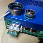
A resolver (stator and rotor part) and an adapter card plugged to Argon

A resolver (stator and rotor part) and an adapter card plugged to Argon

Resolver feedback device will get an official support in the next Argon firmware release. Connecting a resolver to the drive requires few passive components between the feedback device port and actual resolver. These are easily fitted inside the D-sub connector hood and pre-made PCB’s for that will be available for low cost.

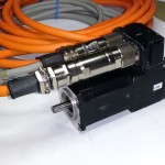
Quite hefty connectors on the motor under test

A bit oversized plugs on the motor under test?

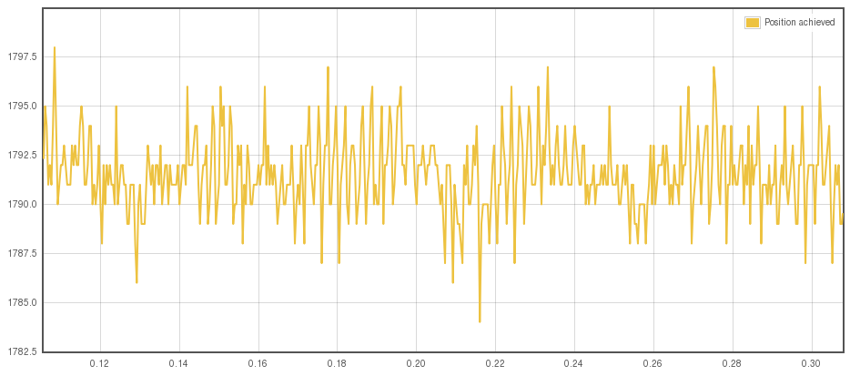
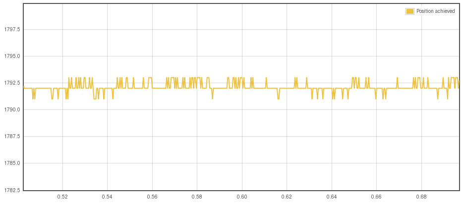
The main concern using analog feedback device (in which category resolver belongs) is the sensitivity to electromagnetic interference. The following images illustrate the importance of proper cable shielding when using resolver. The upper image without cable shielding/screening shows significant amount of position sensor noise which would cause motor hissing and hunting while standing still. The lower image shows nearly ideal stability. In both cases motor is standing still in torque mode, so all we see here is not real movement but just the sensor noise.

Resolver position counter noise when motor or resolver cable shield is present but not connected to drive. Noise amplitude is about 10 counts out of 8192 per revolution.

Resolver position counter noise when motor or resolver cable shield is present but not connected to drive. Noise amplitude is over 10 counts out of 8192 per revolution.

The noise when motor or resolver cable shield is connected at drive end. Noise amplitude has reduced to about 1 to 2 counts out of 8192 per revolution.

The noise when motor or resolver cable shield is connected at drive end. Noise amplitude has reduced to about 1 to 2 counts out of 8192 per revolution.

Random fact of the day: I typically use the most horrible imaginable wiring when developing & testing drives. This serves two purposes: saves time and reveals potential problems early. If it works reliably with bad wiring, then it damn sure will work with a proper wiring.

Servo motor driven laser projector

To demostrate the use of SimpleMotion V2 library with Argon drives, we created a laser projector demo where the angle of two surface mirrors are controlled by two brushless servo motors and Argons.

This was the demo presented also in our SPS IPC DRIVES visit few weeks ago.

Some random project facts:

  • Motor powers are 100W and 300W continuous. Maybe it’s the most overpowered laser projector made.
  • The surface mirrors are cut from hard disk drive platters.
  • The smaller motor doesn’t have full smoothless any more as it was partially burned by accidentally swapping the motor cables causing too much current to it.

Argon firmware 1.2.0 yields better servo stiffness

Argon firmware package 1.2.0 has been released today featuring a breakthrough in servo bandwidth. This has been achieved by significantly reducing the motor feedback sensor propagation delay from read-out to control algorithm. In practice, this allows tuning higher gain values to the motor and achieve higher servo stiffness. This is especially useful in low inertia systems where machine inertia has low stabilizing effect.

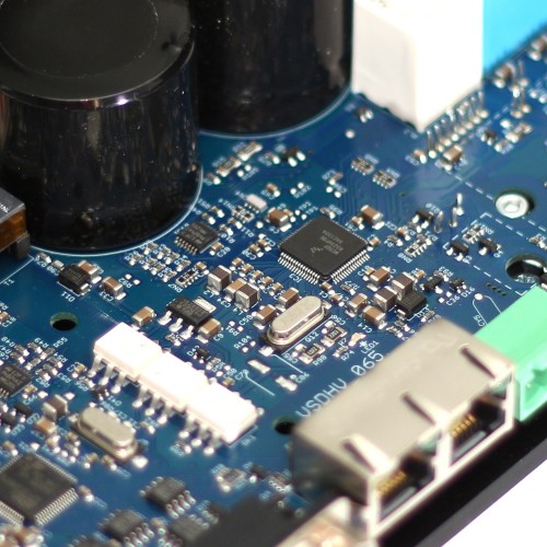
ARGON circuity

ARGON circuity

For full list of changes and download, visit the Wiki page.

Resolver/synchro feedback support in the next FW

I have been testing a resolver feedback couple of days now for Argon and it seems promising already! It’s working very well in the prototype code and it provides position resolution of 8192 counts per revolution.

As resolver is analog sensor, it’s sensitive to noise sources such as unshielded motor leads but this doesn’t seem to be huge problem. Motor will make some hissing sound but otherwise it “feels” just like encoder. However unlike incremental encoders, resolver is absolute position sensor (meaning that the instantly drive knows absolute motor angle, not just the amount turned from the beginning of measure). The benefit of this is elimination of the need of Hall sensors and/or phasing during drive power-on initialization.

SimpleMotion V2 library pre-release with an example program

Things are pushing forward regardless of being very busy preparing Granite Devices visit to SPS IPS DRIVES exhibition (welcome to Nurember, Germany on 26-28.11.2013!).

Anyway, today I have uploaded the first pre-release of awaited SimpleMotion V2 library with a small example program. Download it, and find usage instructions from here. Official library release and more example programs will follow later on.

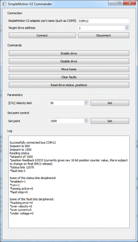
SimpleMotion V2 example program

Easily extendable SimpleMotion V2 example program is currently capable of doing some basic functions

Coming firmware changes & Sanyo Denki P5 example

New Argon servo drive firmware is under preparations. One of the improvements will affect to performance at high electrical commutation frequencies. High frequencies occur at high rotation speeds especially if motor magnetic pole count is high (more than 4).

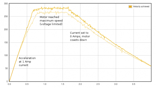
Argon performance improvement illustrated. In this test motor was accelerated with constant current in torque mode before and after FW upgrade. The new FW accelerates motor faster and yields higher speeds meaning it delivers more torque at high speed region.

Performance change illustrated. In this test motor was accelerated with constant 1 Amp current in torque mode before (the light yellow graph) and after FW upgrade (dark yellow). From the graph we can see how the new FW accelerates motor faster and reaches higher speeds meaning it delivers more torque at high speed region. The motor is a 300W Sanyo Denki P5.

Before releasing it, we’re planning to implement also configurable motor braking control that will help people with vertical axes where gravity tends to pull unpowered axis down.