Servo drive internal construction

For those who are interested to see how servo drive internals are constructed, see the new Wiki article: Signal path of servo motor drive. The diagrams presented in the article are useful when designing systems where servo drives are part of the system.

Signal path from setpoint source (user interface) to internal setpoint (fed to actual servo control)

Signal path from setpoint source (user interface) to internal setpoint (fed to actual servo control)

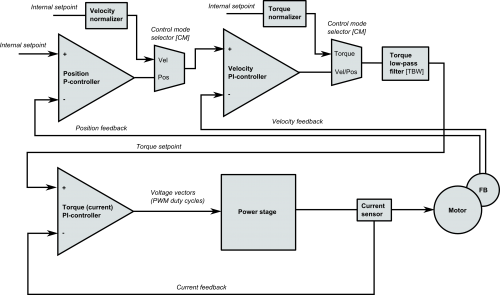
Drive block diagram that applies to all GD drives starting from VSD-E

Drive block diagram that applies to all GD drives starting from VSD-E

The diagrams are also useful when designing custom code to Argon open source I/O side firmware. The I/O side microcontroller acts as provider of User setpoint as well as position and velocity feedbacks referred in the images. Rest of the illustrated logic lies inside the GraniteCore.

The new beginning!

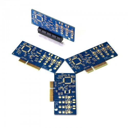
Today the first prototype PCB’s of upcoming Ion servo drives have arrived! Ion will fill the void in the smaller drive range and will lead to cost efficient solution for sub-400 W power class. Ion exhibits 64 pin PCI-Express card edge connector (not electrically PCI-e) allowing design of multi-axis “motion motherboard” with easily interfaced connectors.

The first Ion model has been designed for 5-55 VDC supply voltage and 5 A continuous current. Ion has four power lanes which makes it possible to drive also stepping motors.

The very first Ion servo drive circuit boards

The very first Ion servo drive circuit boards waiting to be equipped

Random Ion PCB facts:

  • 6 signal layers
  • Trace/space 6 mils
  • 526 drilled holes, smallest 0.15 mm
  • 139 surface mount components (double sided assembly)
  • 600+ solder joints
  • Size 71×36 mm