Argon Firmware & Granity version 1.1.0 released

A new Argon firmware has been released today. Version 1.1.0 adds few new functions and among other adjustments, it includes the performance increase discussed in the earlier post.

Granity software

Granity servo tuning software

Full change logs and download can be found from the Wiki (Firmware, Granity).


Update: Turned out there was a clitch in one of the new features. FW version 1.1.1 has been released to address that.

Coming firmware changes & Sanyo Denki P5 example

New Argon servo drive firmware is under preparations. One of the improvements will affect to performance at high electrical commutation frequencies. High frequencies occur at high rotation speeds especially if motor magnetic pole count is high (more than 4).

Argon performance improvement illustrated. In this test motor was accelerated with constant current in torque mode before and after FW upgrade. The new FW accelerates motor faster and yields higher speeds meaning it delivers more torque at high speed region.

Performance change illustrated. In this test motor was accelerated with constant 1 Amp current in torque mode before (the light yellow graph) and after FW upgrade (dark yellow). From the graph we can see how the new FW accelerates motor faster and reaches higher speeds meaning it delivers more torque at high speed region. The motor is a 300W Sanyo Denki P5.

Before releasing it, we’re planning to implement also configurable motor braking control that will help people with vertical axes where gravity tends to pull unpowered axis down.

Important bug fix in Argon FW 1.0.3

We have encountered a flaw in the Argon firmware that puts drive power stage transistors in danger if safe torque off (STO) was activated in certain conditions. This issue has been fixed in a firmware version 1.0.3 available here. Please upgrade FW before continuing use of the drives!

The bug endangered only the drive itself. Regardless of this issue, STO function has always worked without compromising user or machine safety. STO is based on hardware circuits thus software can’t defeat it even if it wanted so.

Safe torque off testing once STO2 activated. When STO2 is activated, the gate drive voltage will be removed from the power stage forcing all motor driving transistors non-conductive. Traces: green=gate supply voltage, red=PWM signal from DSP to power stage, yellow=under voltage fault from power stage, blue=output voltage of power stage (measured at motor terminal).

Safe torque off testing once STO2 activated. When STO2 is activated, the gate drive voltage will be removed from the power stage forcing motor driving transistors in non-conductive state. Traces: green=gate supply voltage, red=PWM signal from DSP to power stage, yellow=under voltage fault from power stage, blue=output voltage of power stage (measured at motor terminal). From the traces we see that STO2 reacted within 300 µs from activation.

The technical background in this issue was that the power stage module’s built-in under voltage lock-out protects only half of the transistors inside. The other half of transistors are able to run despite gate voltage being too low which could cause high heat dissipation and transistor melt down. This has been fixed by shutting down the controlling PWM signal once power stage’s undervoltage fault becomes active.


In the other news, we finally received more Argon in stock! All pending orders will ship on Monday.


Update 26.9.2013: The users who had drives damaged due to this bug have been successfully served by repairing or replacing the drives for free. Such faults are always covered by warranty.

Argon firmware 1.0.2 released!

Argon firmware 1.0.2 has been released containing many significant changes. It can be downloaded from here. At the same time also Granity 1.0.2 has been released to add support for the new features.

One of the most notable change is re-calibration of dead-time distortion correction yielding significantly better servo performance. The earlier firmware was actually calibrated for one of the prototype drives while the latest release has been optimized for the final drive version featuring faster IGBT transistors in the power stage.

dasdas

Dead-time distortion correction in action. The result is near pure sinusoidal current waveforms.

Official Granity and Argon user guide now out!

The first official release of Granity software, Argon user guide and Argon firmware has been just published! To begin, read through the Argon user guide, download Granity from here and the latest firmware from here.

There may be (and probably is) some gaps in the documentation and software bugs at the moment, so be careful! Feel free to leave comments and even contribute to the Wiki directly.

Blinking LEDs

Argon has two programmable front panel LEDs that indicate the state of drive. Having just 2 LEDs is challenging as there are more than dozen different states that need to be distinguishable. The current solution looks like this.

The present way is to assign orange led solely for faults and green led for motor control sate. To fit large number of states in reasonably short and easy to read blinking sequences, we’re blinking them by combinations of short and long flashes. One state for example can be repeating pattern of short-short-long-pause and another long-long-short-short-pause.

LED blinking example. The sequence here is long-short-short-pause.

LED blinking example. The sequence here is long-short-short-pause.

The Wiki page (link above) has animated images from each combination making them hopefully easier to identify. What do you think about this approach (please leave a comment)? Another alternative I have been pondering is just flashing led certain number of times. Such as one state is 3 flashes, another 4 flashes. The problem is counting reliably something like 15 flashes.


Meanwhile in production: the first release candidate Argon batch should arrive any time now! Last week factory reported mistake of getting wrong type of bridge rectifiers which caused 2-3 days delay to planned schedule but drives should definitely arrive this week for final testing.

Resetting STM32 option bytes

Without too much thinking I wrote a code to Argon’s STM32 ARM processor that write protects its flash content. After a minute I encountered a problem that I was unable to program anything new to the chip as it protects writing into memory also with a debugging tool effectively bricking the device. It took an hour to figure out how to restore the chip option bytes that determine if the flash memory is protected or not. JLink’s small utility that is supposed to restore STM32 option bytes didn’t appear to work for write protection so alternative solution was necessary to avoid replacing the chip on PCB.

After some googling (found this useful forum post) and reading chip data sheets I figured out how to do it manually with JLink Commander tool. I’m posting JLink command list here as I’m sure there are people needing this info, too.

(unprotect option bytes)
w4 0x40023c08,0x08192A3B
g
halt
w4 0x40023c08,0x4C5D6E7F
g
halt

(restore non-write protected state. one could also reset other option bytes here such as read protection or brown out reset settings by modifying the next line)

w2 0x40023C16,0xffff
g
halt

(write option bytes)
w1 0x40023C14,0xef
g
halt

I’m not sure if g and halt commands are necessary but used them just in case. This should work at least with STM32F2 series and probably also STM32F3 and STM32F4 chips too.

JLink Commander when unlocking STM32F2 write protection

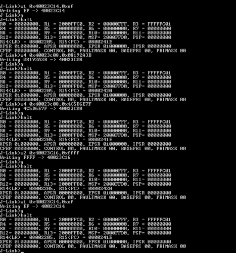
JLink Commander screenshot after unlocking STM32F2 write protection

Precision crafting of the Bootloader

Bootloader (a.k.a. IAP = in application programmer or DFU = device firmware upgrader) is a piece of software in microcontroller to make programming of a new firmware inside the device possible without accessing the chip physically with a programming tool. In Argon’s case firmware upgrade will be possible through the SimpleMotion port and Granity software.

I have spent couple of last days finalizing the bootloader of Argon. Even though the amount of code is small, it must be written with extreme caution because a bootloader bug could lead to bricked device that need to be re-programmed in the factory, or worse, induce permanent damage to hardware. Bootloader is also the part of software that cannot be upgraded by the end user, so we have no change to fix the possible bootloader mistakes remotely after devices are shipped.

In our goals, bootloader must be robust enough to make it impossible to brick the device. This includes the cases where incorrect or corrupted firmware is being sent, or power is being cut in the middle of the firmware upgrade process. Bootloader should be also tolerant for some hardware errors, such as broken crystal oscillator.

About that feedback device port

The feedback device port of Argon has “only” 15 pins, just like earlier drive model VSD-E, but tons of more of more capabilities have been squished into it. It has:

  • 5V 500 mA output
  • 5 differential input lines where 3 of them are bidirectional
  • 3 single-ended digital inputs
  • 2 differential 1 Vpp analog inputs
  • Differential inputs may be used with single ended signals as well

All this makes it possible to support many kinds of feedback devices such as:

  • Quadrature encoder with index channel
  • SinCos encoder with interpolation factor up to 1000x
  • Tachometer
  • Resolver (a.k.a. synchro)
  • Hall sensors
  • Serial encoderes (SSI, BISS etc). Support for example for Austria microsystems low cost magnetic linear & rotary encoders possible.

VSD-E could support only the first of them so I think the progress is quite significant.