Servo motors running synchronized

A video showing two servo motors being controlled independently & synchronized over RS485 based field bus. A small custom C++ software is generating the trajectory points independently for each axis and feeding the points to servo drive command buffers. Drives execute commands from buffer based on their internal clock yielding gapless and smooth motion even when PC is under load.

Both axis are fed 1250 position commands per second and tracking error value is read back at same rate and displayed on the PC screen. The software has a buffer monitor widget that shows how much data drive buffer currently has. Everything is fine as long as buffer doesn’t go empty which would cause a break in motion.

The app has merely 200 lines of code. I’m planning to extend it to run G-code after Argon drives are out.

New logic circuit PSU transformer

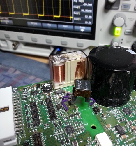
I call back that last update (see previous post). Apparently the transformer wasn’t sufficient after all due to lack of mechanical protection of windings. The safety standard for transformers, EN 61558-1, requires that insulation must not be easily damageable during device assembly. So windings must be mechanically protected from being hit by other objects.

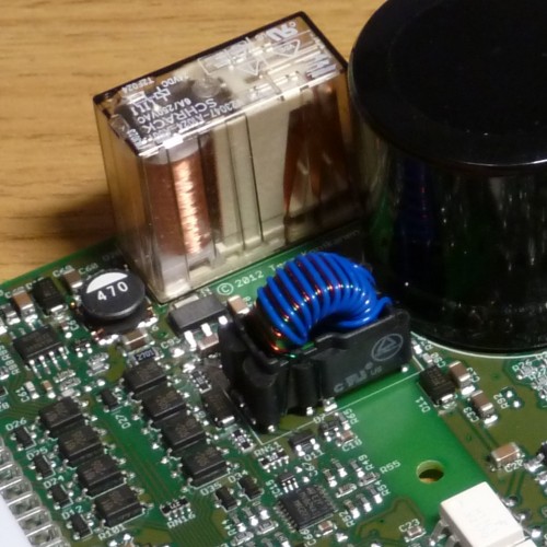
Luckily I found near perfect “drop-in” replacement for the transformer. This model actually probably would have been chosen in the first place if it were available at the time of logic circuit PSU design. The new transformer type was just introduced to market at late 2012.

The new transformer mounted with "3D" installation method

The new transformer mounted using the “3D” installation method familiar to all tinkerers

Safety checking results

Today I got first results from the accredited testing service for compliance of power drive safety standard EN 61800-5-1. They did good job and found few issues:

  1. Isolating transformer between user touchable and hazardous voltage side doesn’t meet reinforced isolation requirements
  2. Clearance from power stage & bridge rectifier mounting screws to PCB tracks not large enough
  3. On one side of the enclosure the vent holes are too large to meet IP30
Isolating transformer (blue) has 3 kV isolation spec

Logic power isolating transformer (blue) has 3 kV isolation spec but still doesn’t meet the strictest interpretation of  the safety standard

Luckily none of them is hard to fix but finding them early was very important!

Update

By contacting transformer manufacturer we learned that the blue winding consists triple insulated teflon wire which fulfills the reinforced isolation standards. If we can confirm that, we save few days of isolated PSU circuit redesign & testing!

Laser diode drivers & Quick update

This week I have been wandering around Photonics West exhibition at San Francisco. I have been collecting leads for our new product area: laser diode drivers. LD drivers are a natural expansion to motor drives category as they share many of the closed loop current control technologies. Check out Intensify Nx50 product site!

Intensift Nx50 laser diode driver

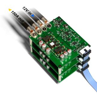
Intensify Nx50 laser diode driver

Meanwhile Argon prototype has been sent to a reputable standard verification company to ensure it’s compliance to EN 61800-5-1 safety stadard. Safety is a highly critical part to get correct as failures to comply could become very expensive. Granite Devices is taking product liability seriously.

Finding drive power limits

Lately I have been concentrating on finding the current & power limits of the Argon drive. I have used the artificial load unit as test load.

Testing has gone well and has revealed things I didn’t know about Argon. The most positive surprise is that the drive seems to be able to deliver a lot more continuous power than calculated. The first anticipated limiting factor in the design was the equivalent series resistance (ESR) of the bulk capacitors. ESR sets the limit to the maximum ripple current that AC-to-DC power supply can handle because current flowing through capacitor’s internal resistance will heat them up and eventually make them reach their maximum safe temperature.

By calculating maximum ripple current & power based on capacitor specs I came up with figure of 700W continuous power before capacitors get too hot (105⁰C). However, by testing I found out that even at 1200W continuous output the caps didn’t get warmer than 37⁰C. I think capacitors either are way better than specified or their ESR is specified at 105⁰C which may be much higher than the ESR in room temperature. So 700W is probably the limit when capacitors already run hot (needs very high ambient temperature) and at least 1.2kW may be extracted at room temperature.

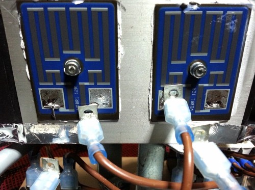
Power resistor fused open as terminals desoldered them selves

Oops! Artificial load unit power resistor wire terminals desoldered them selves under little bit too much pressure

Feels very solid

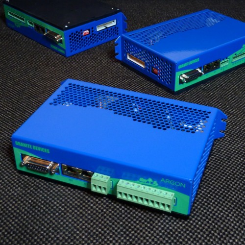
We finally have received the samples of enclosure consisting steel sheet metal cover and aluminum heat sink plates. So the front panel art comes with trees as voted best in the previous posts. My thanks to everyone giving comments to that post! It really helped us to make the best choice.

Argon prototypes with industrially made covers

Argon prototypes with industrially made covers. LED numbering texts (above the RJ45 sockets) were mistakenly forgotten from the front panel art.

The cover slips on smoothly unlike the first self made prototype which required bending one side in order to install it on the device. The realized design looks and feels very solid and leaves only little space for improvement. However, few improvements will be carried out mainly to help assembly, most of them being related to threading for mounting screws and adding more accuracy to bends.

To the final design I’m also considering to add an placeholder hole for possible extension port that could be installed inside the drive as stack-on circuit board. Extension boards could be made by end users, third parties and of course by us.

Surviving lightning strikes

Today I went into the lab to repeat some surge tests that let the smoke out of Argon’s on-board voltage regulator the last time. This time some circuit modifications were made as attempts to enhance the surge voltage & current handling. Surge test attempts to emulate a lightning strike.

Total of 12 a bit different surge pulse tests cases had to be carried out to meet the EN 61000-6-2 and EN 61000-4-5 industry standards. In the list below are the open circuit voltage and series resistance that are shot to the target voltage supply lines:

  • + and – 500V 2Ω between 24V and 0V (DC supply)
  • + and – 500V 12Ω between  +24V input and chassis (DC supply)
  • + and – 500V 12Ω between 0V input and chassis (DC supply)
  • + and – 1000V 2Ω between L and N (AC input)
  • + and – 2000V 12Ω between L and chassis (AC input)
  • + and – 2000V 12Ω between N and chassis (AC input)

The surge tests are typically more difficult to pass than ESD & EFT due to high injected energy and currents. For instance 500V and 2Ω  produces current of 250A and 1000V 2Ω yields whopping 500 Amperes. That will heat up the overvoltage protectors quite extremely and weaker components simply explode.

Now all tests passed without damage and motor was servoing simultaneously through the whole test. Changes will be brought to the PCB design which makes a big step closer to the final design.

Artificial load

I hope our followers have had a restful Cristmas break and joyful beginning of the new year! Anyway, time to get back to the business.

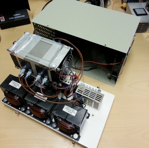
The photo below shows the artificial load unit to be used in Argon production testing process. In other words it will be used to simulate heavy load for drive power stage electronics to separate the wheat from the chaff.

Artifial load unit

Artificial load (work in progress). The most of energy goes into the flat power resistors mounted on the sides of the heat sink block.

The unit consists of three inductors and three power resistors forming a 3 phase load that simulates a motor stator. In the same high density heat sink there is also a fourth power resistor that provides load for regenerative resistor IGBT switch.

Other stuff inside provides power for cooling fans and contactor that safely disconnects the load in case of over heating. The two fans in the heat sink are installed in push-pull configuration for maximum air flow.

Front panel art

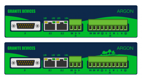
Below is the current state of front panel art of Argon drive. The enclosure will be made out of steel sheet metal + aluminium heat sink plate as bottom. Front side of the drive will have silk screen printed artwork.

Argon front panel art release candidates

Which one of the variations you’d prefer? With some trees or without. Please leave a comment!

Survival course

Yesterday was a day full of sparks – electrostatic discharge sparks. Tests were done by shooting sparks to to different targets including cables, casing and open connectors while the drive was operating. Also various ESD types were tested: contact discharge, air discharge, varying voltages and different polarities. All ESD tests were passed without a single hiccup.
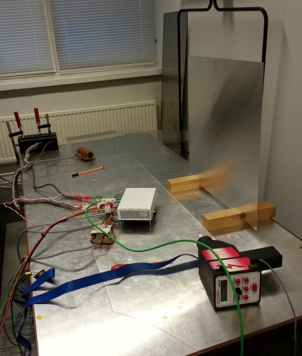
ESD test table and ESD gun

However, ESD is only one mode of high voltage harassment drive must cope with. Another test type is EFT (electrical fast transient) which is induced to cabling through capacitive clamp. Several kilovolts with nanosecond scale rise times were injected as 75 spike bursts into the clamp at frequency of 5 kHz and repeated 10 times. This simulates interference spikes emitted by nearby sparking or EMI. No problems recorded.
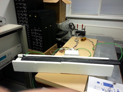
Encoder cable going through capacitive EFT test clamp

The last test was a surge test. A high energy and relatively long pulse were applied to supply voltage inputs. This is typically the most difficult harassment to filter out in electronics.
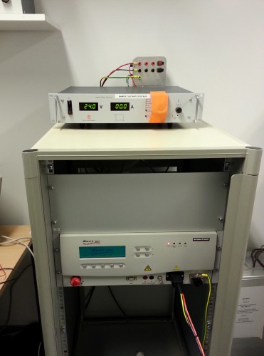
Surge & EFT test equipment – above is the 24V PSU and the device below is the EFT & Surge injector.

Difficulty of surge may be imagined by the funny fact that cheap lab power supplies tend to die during the test even when it’s not the target. So heavy duty PSU had to be used as supply to avoid it breaking.

In this test we found a problem. The voltage regulator of Argon died when shot with 400 V and ~40 A pulse in negative polarity to 24V input. However, drive survived a 500 V positive polarity surge. 500 V is the required level to pass the test. Failing one tests means that some circuit/layout changes has to be done to address the problem.