
Last days we have been working on supporting SinCos encoders. SinCos encoder is exactly like standard incremental encoder, except it has sinusoidal analog outputs instead of digital quadrature waveforms.
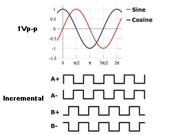
SinCos encoder signals vs digital incremental encoder signals
The beauty of this is that the analog waveform can provide infinite position resolution when the phase angle of signals are calculated. The latest prototype firmware of IONI Pro now supports SinCos interpolation which increases the resolution that we would get from digital counting by the factor of 16, 64 or 256 times. I.e. a 1000 pulse (or cycle) per revolution analog encoder with 256X interpolation yields resolution equal to 256 000 quadrature pulses per revolution (PPR) or 1 024 000 counts/per revolution (actual position resolution of motor).
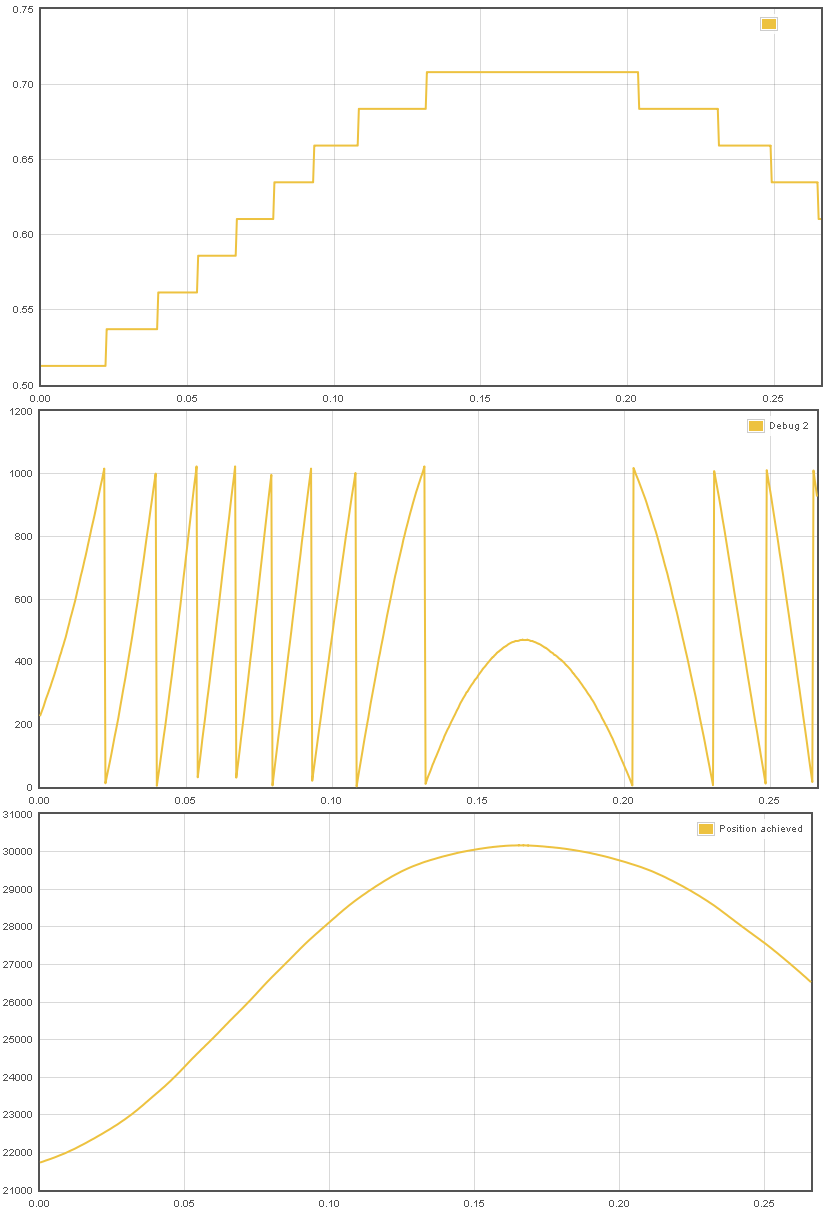
SinCos encoder interpolation: the first graph shows position counter in digital mode, the middle shows interpolated angle from sine and cosine signals and the last image shows the combination of these two to form the high resolution position count.
Very high resolution helps especially to make motion smoother, quieter and stiffer. The initial tests show amazing smooth performance of the motor in velocity and position modes. There was no dithering or groaning noise from the motor and at same time the motor position holding stiffness was jaw dropping. It felt like the motor was physically jammed as the eye, hand or ear can’t notice any movement.
I have been looking forward to this as I have a linear motor with sin/cos feedback. But I have a question:
Since the sin/cos signal is only 1 v p-p do you need some sort of ungodly shielding to avoid noise? With a division of 256, we get about 4 mV steps. I know these are differential signals, but that is still an awfully small amount. Can you give some insight of how that works?
In our test there was no problem with 1 Vpp signal. No noise seen with 256X mode, but this test was done only with single motor. Multiple motors may increase EMI noise but probably not a high concern.
Awesome. At what rate is the position calculated and what is the maximum sin/cos frequency before we miss steps? Linear motors can go awfully fast and that renishaw scale has a cycle length of 20 um…
The sampling algorithm used tolerates very high speeds without even falling back to digital mode. In theory is designed to tolerate at least 500 kHz count rate (but probably over 1 MHz).
In my tests I could not reach the limit speed with 1024 cycle encoder and 3000 rpm motor.
Quickly calculated that this 500 kHz would equal 2.5 m/s with 20 µm cycles.
Way cool! Can’t wait for my units to get here….
Thank you! I was hoping to use motors with sin/cos feedback.
I see you don’t monetize openservodrive.com,
don’t waste your traffic, you can earn extra bucks every
month with new monetization method. This is the best adsense alternative for any type of website (they approve all sites), for more info simply search in gooogle: murgrabia’s tools